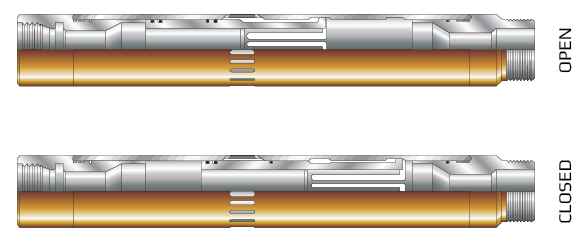
The ESS-ELL Model EL Sliding Sleeve is a downhole device, normally screwed into the production tubing, that allows communication between the tubing and the casing.
The closing sleeve includes bonded upper seals to ensure integrity of the seals for extended periods of time while downhole. They can also be of various elastomer types.
The upper sub has a selective "EF” landing nipple profile machined into it to allow for the proper shifting of the sleeve and to serve as a receptacle for other flow control devices, such as blanking plugs and separation tools.
The ESS-ELL Model ED-2 Shifting Tool is used to shift the EL Sliding Sleeve open and closed. The sleeve is designed so that normal wireline activities will not open or close the sleeve inadvertently. Upward jarring opens the sleeve and downward jarring closes the sleeve.
| SIZE AVAILABILITY CHART* | |||||||||||||
| TUBING SIZE (Metric) | 1.900 | 2.167 | 2.375 | 2.875 | 3.500 | 4.5 | |||||||
| 48mm | 52mm | 60mm | 73mm | 89mm | 114mm | ||||||||
| SEAL BORE (Metric) | 1.43 | 1.5 | 1.56 | 1.62 | 1.78 | 1.81 | 1.87 | 2.25 | 2.28 | 2.75 | 2.81 | 3.75 | 3.81 |
| 36 | 38 | 39 | 41 | 47 | 57 | 58 | 69 | 71 | 95 | 97 | |||
| Seal Bore | 1.43 | 1.5 | 1.56 | 1.62 | 1.78 | 1.81 | 1.87 | 2.25 | 2.31 | 2.75 | 2.81 | 3.75 | 3.81 |
| (Metric) | 36 | 38 | 39 | 41 | 45 | 46 | 47 | 57 | 58 | 69 | 71 | 95 | 97 |
| Length* | 30.53 | 30.38 | 31.97 | 35.28 | 37.66 | 47.75 | |||||||
| MAX O.D.** | 2.375 | 2.500 | 2.910 | 3.410 | 4.500 | 5.500 | |||||||
| Inner Sleeve I.D. | 1.531 | 1.656 | 1.937 | 2.375 | 2.875 | 3.910 | |||||||
| Flow Area | 1.893 in. sq. | 1.893 in. sq. | 2.839 in. sq. | 4.138 in. sq. | 6.106 in. sq. | 11.527 in. sq. | |||||||
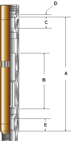
| A | 25.0 | 25.06 | 24.94 | 25.0 | 26.66 | 26.66 | 26.72 | 28.25 | 28.31 | 29.5 | 29.56 | 36.25 | |
| B | 6.09 | 6.09 | 7.97 | 8.28 | 8.75 | 13.125 | |||||||
| C | 4.81 | 4.81 | 5.81 | 6.25 | 6.75 | 7.375 | |||||||
| D | 1 | 1 | 1 | 1 | 1 | 1 | |||||||
| E | 4.69 | 4.75 | 4.81 | 4.88 | 5.66 | 5.69 | 5.75 | 6.12 | 6.19 | 6.66 | 6.72 | 6.46 | 6.54 |
* Length may vary depending on the type of thread used.
** Maximum OD may be greater if special threads are used.
ASSEMBLY: